> For the complete documentation index, see [llms.txt](https://docs.timeinpixels.com/llms.txt). Markdown versions of documentation pages are available by appending `.md` to page URLs; this page is available as [Markdown](https://docs.timeinpixels.com/nobe-omniscope/scopes/vectorscope.md).

# Vectorscope

The Vectorscope plots **chrominance** on a circular graph — hue as angle from 0°, saturation as distance from the center (which represents gray). Use it to evaluate color balance, skin-tone accuracy, and broadcast-legal saturation.

The classic vectorscope is a plot of the **Cb / Cr** plane of Y'CbCr — the two color-difference signals that, together with luma (Y'), fully describe a video picture. "Zero chroma" is the center point, which is why neutral gray, white, and black of every level all collapse to a single dot there.

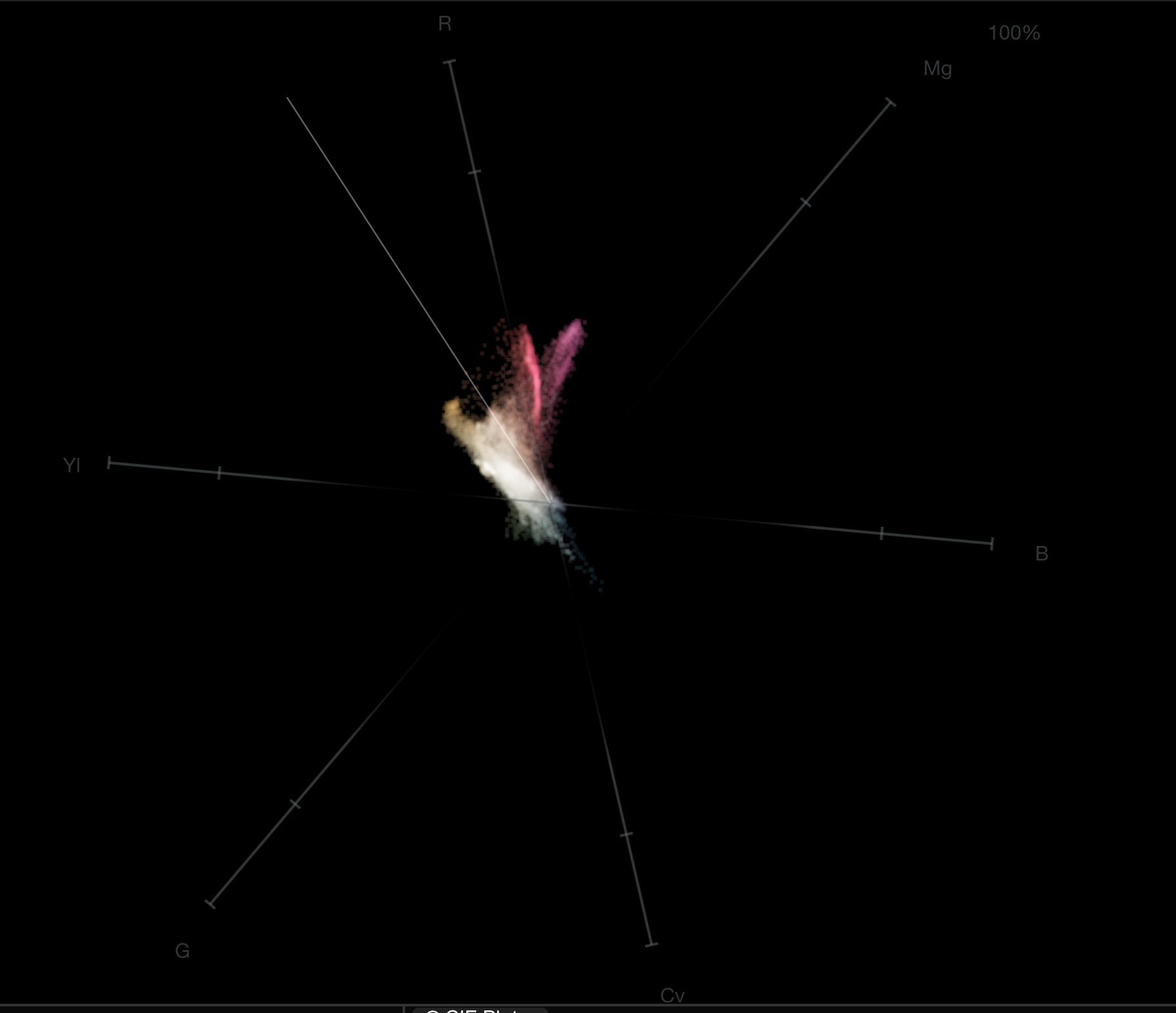
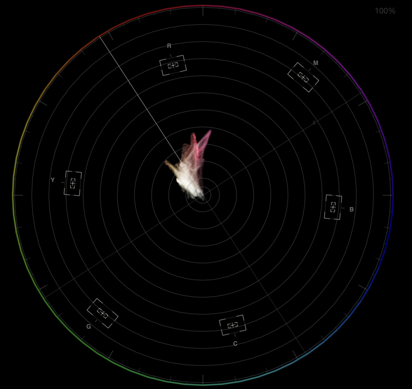
<figure><img src="/files/AOPE956w1HS1GpjwXFzC" alt=""><figcaption><p>Vectorscope with 75 % targets, skin-tone line, and I/Q guides</p></figcaption></figure>

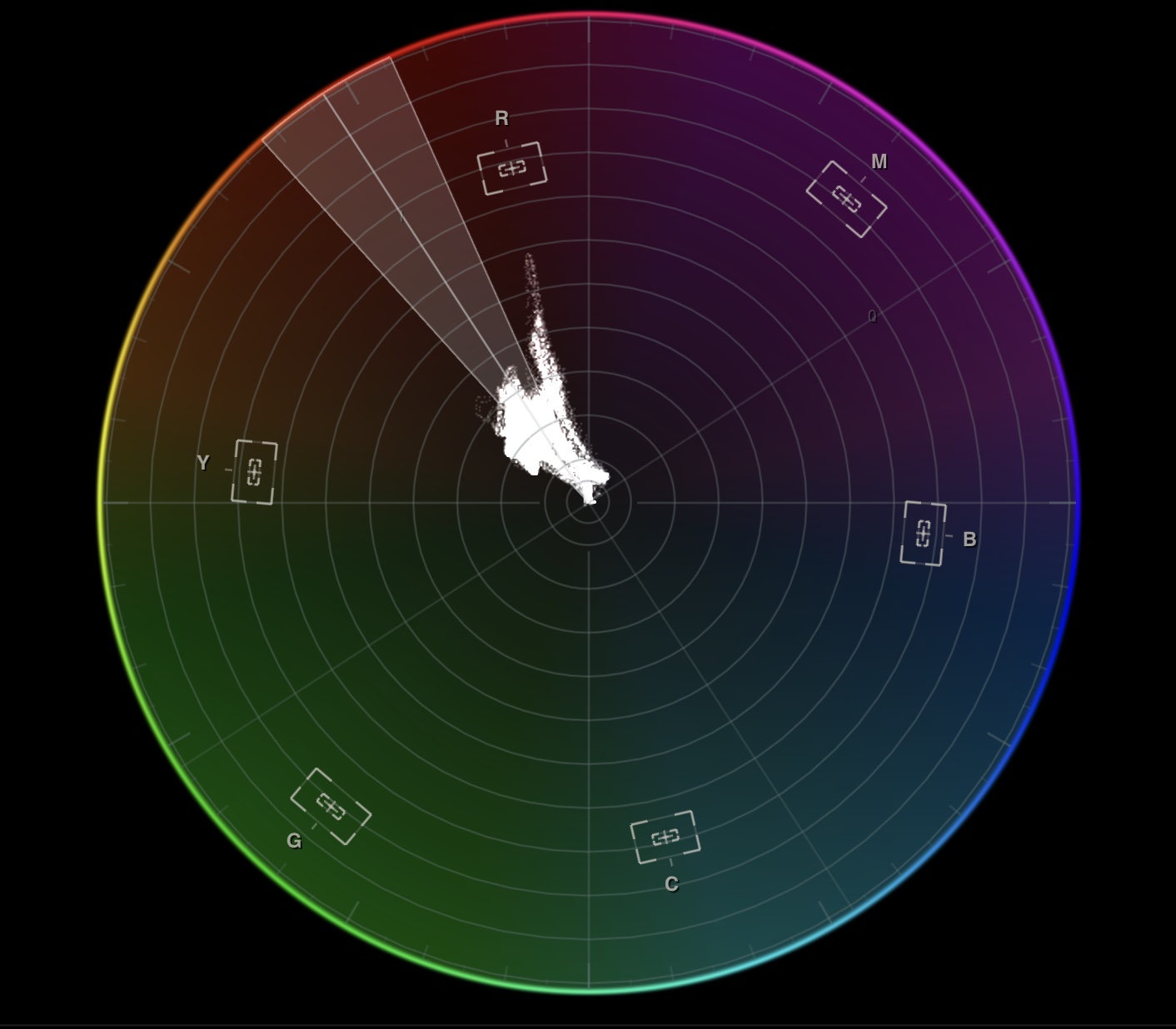
<figure><img src="/files/EoWCxJh2N7h7Vl9jyHMK" alt=""><figcaption><p>Vectorscope features: Color Wheel mode, hexagonal rings, trace outline, skin-tone tolerance band, improved target indicators, and I/Q lines</p></figcaption></figure>

## Transform Modes

| Mode    | Description                                               |
| ------- | --------------------------------------------------------- |
| **YUV** | Classic broadcast vectorscope (CbCr plane). Default.      |
| **HSL** | Saturation-weighted projection — useful for look-dev work |

You can switch **Orientation** to the alternate rotation mode in either transform mode. For a color-wheel-style orientation, use **HSL** transform with the alternate orientation mode.

## Zoom

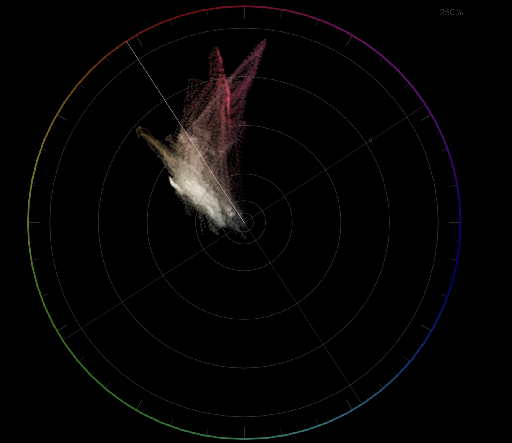
Zoom into the center of the plot for fine color-balance work or expand to see the full gamut.

| Input                                | Action                     |
| ------------------------------------ | -------------------------- |
| **Mouse wheel**                      | Zoom in / out (continuous) |
| **Middle-click** or **Double-click** | Reset to 100 %             |

<figure><img src="/files/qPOdhAZmexgXlfAE8vtv" alt=""><figcaption><p>Zoomed vectorscope for precise color balance inspection</p></figcaption></figure>

Context-menu presets: **100 %** and **200 %** for quick switching.

### Input Gain

Boost the trace intensity to reveal low-saturation detail.

| Input                                               | Action              |
| --------------------------------------------------- | ------------------- |
| **Mouse wheel** (with **Mouse wheel gain** enabled) | Adjust gain (1×–5×) |
| **Middle-click** or **Double-click**                | Reset gain to 1×    |

Enable **Mouse wheel gain** in the scope settings to switch the scroll wheel from zoom to gain control.

## Graticule & Guides

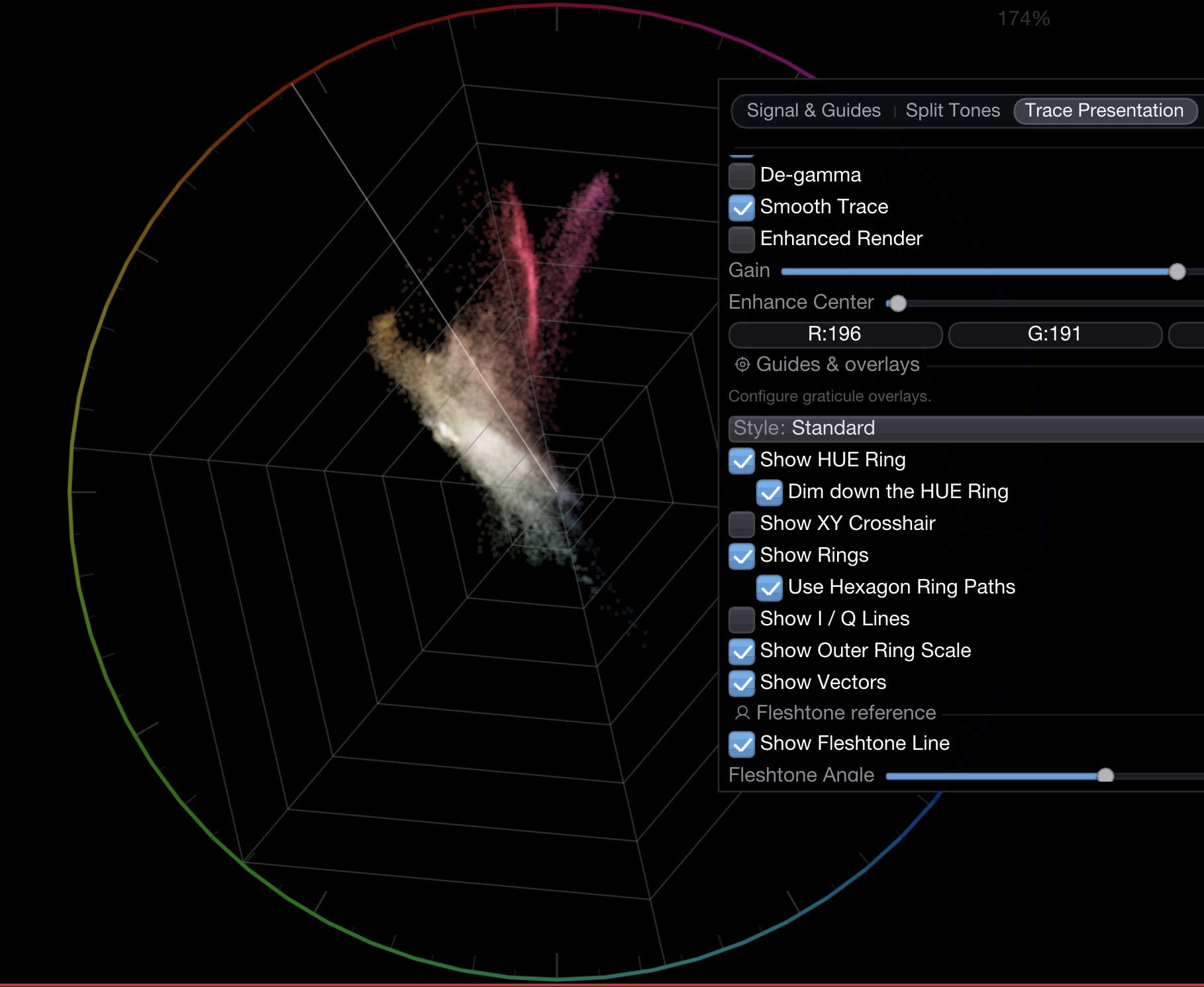
<figure><img src="/files/wt0yx3QY7ENx9L4MIeBt" alt=""><figcaption><p>Graticule and guide settings</p></figcaption></figure>

### Graticule Style

| Style           | Description                                                |
| --------------- | ---------------------------------------------------------- |
| **Standard**    | Circular rings with crosshair, I/Q lines, and target boxes |
| **Hue Vectors** | Gradient-based hue visualization with directional vectors  |
| **Color Wheel** | Full color wheel background for intuitive hue reference    |

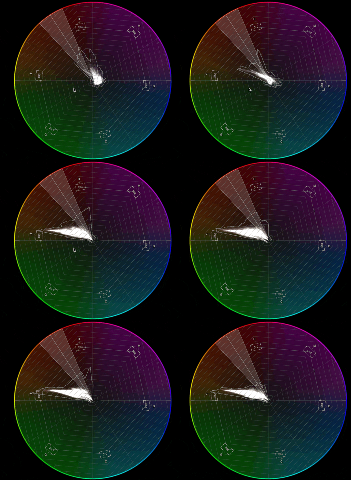
<figure><img src="/files/oYMcwj0FEqI0HQHx7Tbc" alt=""><figcaption><p>Hue Vectors graticule style</p></figcaption></figure>

<figure><img src="/files/M8MpHm5DvmbI4JF8x5q0" alt=""><figcaption><p>Color Wheel graticule style</p></figcaption></figure>

### Guide Elements

| Guide              | Description                                                                      |
| ------------------ | -------------------------------------------------------------------------------- |
| **HUE Ring**       | Color wheel around the outer edge. Can be **dimmed** for less distraction.       |
| **Crosshair**      | X/Y axis lines through center                                                    |
| **Rings**          | Saturation reference rings. Toggle between **circular** and **hexagonal** paths. |
| **I/Q Lines**      | In-phase / Quadrature axis guides                                                |
| **Outer Scale**    | Tick marks around the outer ring                                                 |
| **Vectors**        | Broadcast color-bar target markers                                               |
| **Skin-tone Line** | Configurable reference line at a user-defined hue angle (default 123°)           |

### Skin-Tone Indicator Band

The skin-tone line can be expanded into an optional tolerance band. This helps you quickly see whether skin hues stay close to your chosen reference angle.

| Setting                  | Description                                                              |
| ------------------------ | ------------------------------------------------------------------------ |
| **Show Fleshtone Line**  | Enables the skin-tone reference axis                                     |
| **Fleshtone Angle**      | Sets the reference angle (0–359°, default 123°)                          |
| **Show Tolerance Band**  | Draws a shaded angular band around the reference line                    |
| **Tolerance**            | Band half-width in degrees (±1° to ±45°; common values are ±10° or ±20°) |
| **Tolerance Band Color** | Adjust band color and opacity for visibility                             |

<figure><img src="/files/xsjVaUMb8gBEgxaQauCh" alt=""><figcaption><p>Skin-tone tolerance band on the vectorscope</p></figcaption></figure>

Interpretation: trace energy inside the band is within your current skin-tone tolerance; trace energy outside the band indicates hue drift from that reference.

### Broadcast Targets

| Target    | Description                                   |
| --------- | --------------------------------------------- |
| **75 %**  | Standard 75 % color-bar targets (default: on) |
| **100 %** | Full-level color-bar targets                  |

Target color and position are derived from the active color space.

## Trace Presentation

| Setting                          | Description                                                                                                                                                                                                                                                                                                                                                                                                                                         |
| -------------------------------- | --------------------------------------------------------------------------------------------------------------------------------------------------------------------------------------------------------------------------------------------------------------------------------------------------------------------------------------------------------------------------------------------------------------------------------------------------- |
| **Colorize**                     | Tint the trace with per-pixel color (vs. monochrome)                                                                                                                                                                                                                                                                                                                                                                                                |
| **Linearize trace** ("De-gamma") | Apply the inverse EOTF to the trace-density accumulator so that the visual brightness of the plot follows light-linear energy instead of the non-linear R'G'B' code values. Makes shadow-region and highlight-region saturation appear with similar visual weight — useful for log or HDR signals where a raw trace would be dominated by midtone density. It does **not** change the chroma position of any sample, only how brightly it is drawn. |
| **Smooth Trace**                 | Temporal blend for a cleaner, less noisy look                                                                                                                                                                                                                                                                                                                                                                                                       |
| **Enhanced Render**              | Line-strip rendering instead of point cloud                                                                                                                                                                                                                                                                                                                                                                                                         |
| **Gain**                         | Master trace brightness (0.02–3.0)                                                                                                                                                                                                                                                                                                                                                                                                                  |
| **Enhance Center**               | Extra gain applied to the low-saturation core (0–12)                                                                                                                                                                                                                                                                                                                                                                                                |

### Highlight Trace Edges

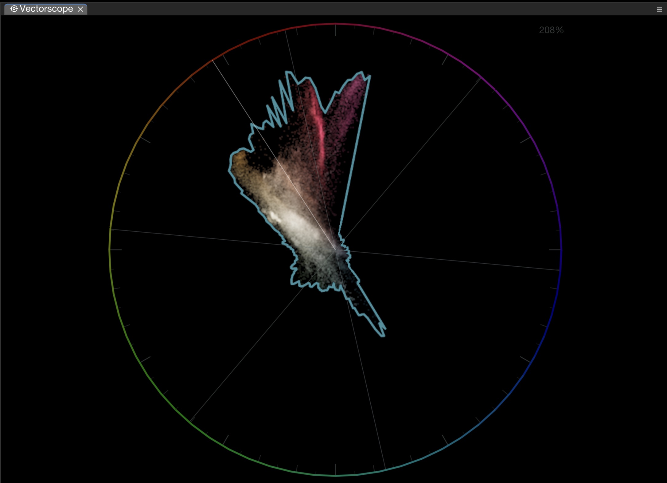
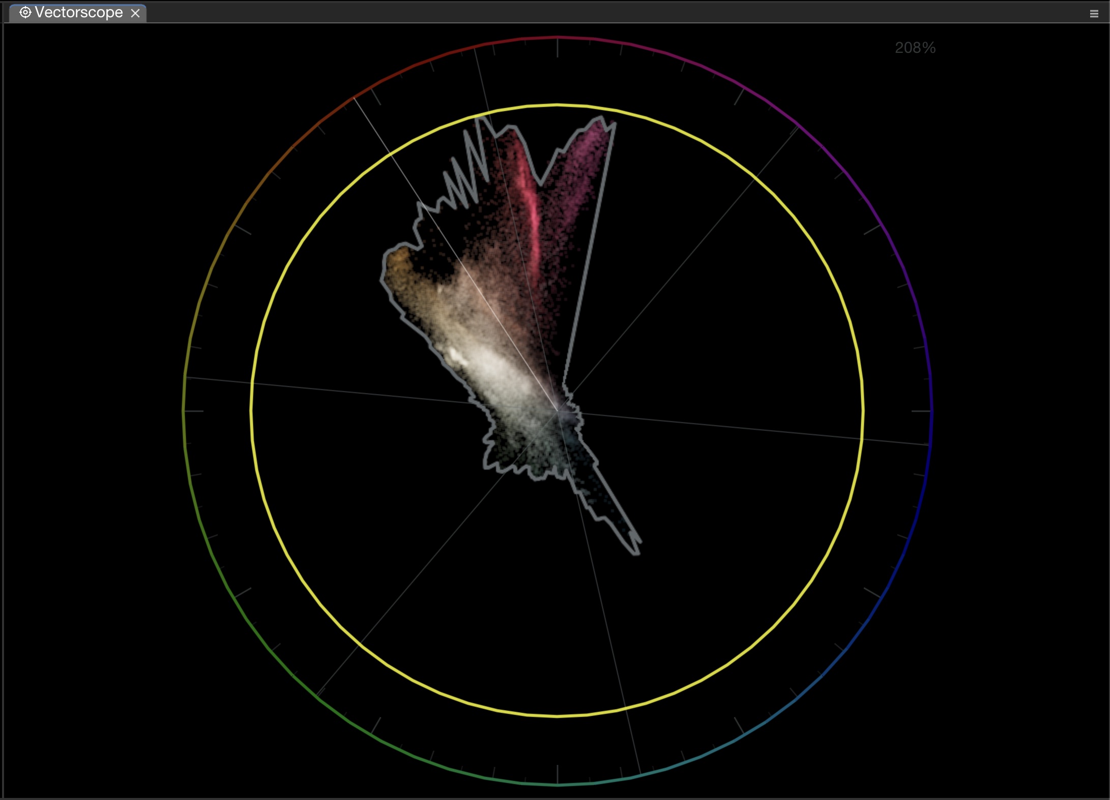
Render a colored outline at the outermost boundary of the trace — highlights the signal extent at a glance.

<figure><img src="/files/HLOgyi8LGWmdhhc6MD6R" alt=""><figcaption><p>Trace edge highlight showing signal boundary</p></figcaption></figure>

## Split Tones (L/M/H)

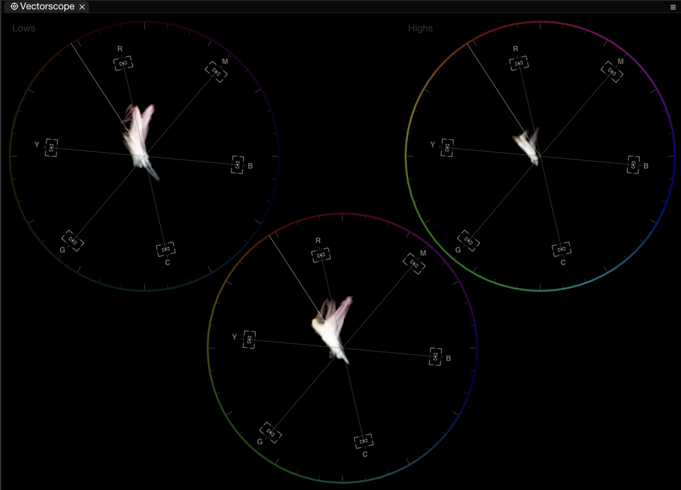
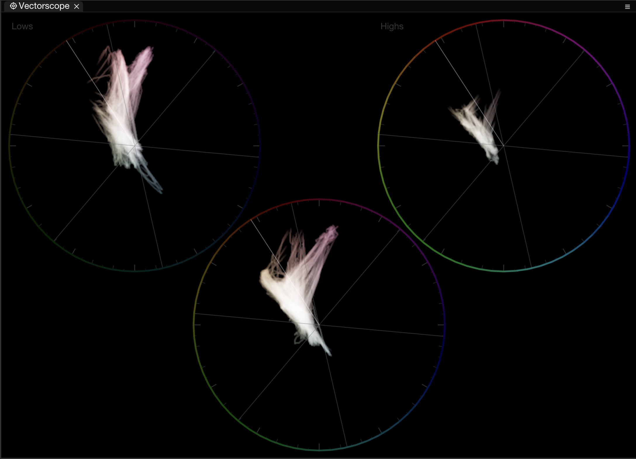
Split the trace into three independent **Lows / Mids / Highs** buckets, each drawn in its own circle. Buckets are defined by **luma** (Y', the weighted R'G'B' sum — not scene-linear luminance), so the split follows the same tonal perception a colorist uses when talking about lift / gamma / gain. This reveals how color shifts across shadow, midtone, and highlight regions.

<figure><img src="/files/feUxgbAKMDf15sAKuMED" alt=""><figcaption><p>Vectorscope in L/M/H split mode</p></figcaption></figure>

<figure><img src="/files/yWAlXPJ2OjaelqSYCnpQ" alt=""><figcaption><p>L/M/H split with Color Wheel graticule</p></figcaption></figure>

| Setting             | Description                                    |
| ------------------- | ---------------------------------------------- |
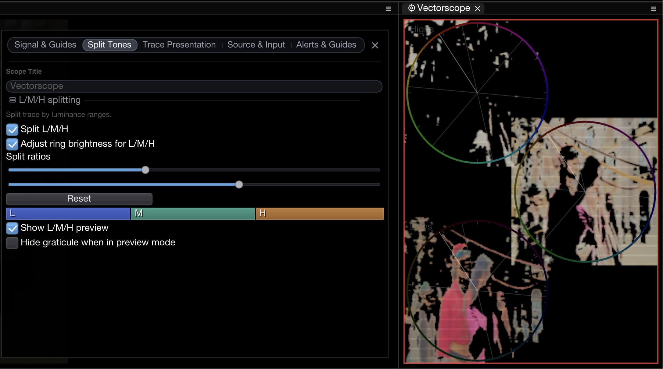
| **Split L/M/H**     | Enable the three-way split                     |
| **LM ratio**        | Boundary between Lows and Mids (default 33 %)  |
| **MH ratio**        | Boundary between Mids and Highs (default 66 %) |
| **Ring brightness** | Adjust graticule brightness per bucket         |
| **Enhanced render** | Sharper rendering for split view               |

### L/M/H Preview

Hold **Alt** to see a false-color overlay on the Source Signal showing which pixels fall into each luma range — blue for lows, green for mids, red for highs.

<figure><img src="/files/YE1EeTaTORIOdKjq9M8w" alt=""><figcaption><p>L/M/H preview overlay showing luminance ranges on the source image</p></figcaption></figure>

### Zoomed L/M/H

Use the standard vectorscope zoom controls while inspecting the split circles.

<figure><img src="/files/TtN865h65phvbX6j19UP" alt=""><figcaption><p>Zoomed L/M/H split — focus on mids</p></figcaption></figure>

### Luma Range Clamp

Instead of splitting into three buckets, clamp to a **single luma range** using the **Min / Max** sliders. Only pixels whose Y' falls within the range are plotted — useful for isolating the color of skin pixels, of highlights alone, or of a specific zone of the image without masking.

## Saturation Alerts

Set thresholds to flag illegal or excessive saturation levels.

<figure><img src="/files/7I7BSeFb4NO18CU3kyjX" alt=""><figcaption><p>Saturation alert ring and max ring indicators</p></figcaption></figure>

| Alert          | Description                                                                                                                                    |
| -------------- | ---------------------------------------------------------------------------------------------------------------------------------------------- |
| **Alert Ring** | Colored ring at a configurable saturation threshold. Signal exceeding it triggers a visual warning. Drag the ring interactively to reposition. |
| **Max Ring**   | Tracks and displays the absolute maximum saturation contour in real time                                                                       |
| **Outline**    | GPU-rendered trace boundary with anti-aliasing. Use the **Outline Thickness** slider to adjust the rendered width (0.5–5 px).                  |

Each alert has a customizable **color**.

## Low-Pass Filter

Enable **Low-Pass filter** to apply a horizontal box blur to the trace, reducing noise and making trends easier to read. Adjustable kernel size (0.5–20).

## Global Targets

[Global targets](/nobe-omniscope/features/global-targets.md) appear as RGB reference points on the vectorscope, providing shared color targets across all scopes and layouts.

## Color Pins

When color pins are placed on the [Source Signal](/nobe-omniscope/scopes/source-signal.md), they appear as markers on the vectorscope at the corresponding hue/saturation position.

<figure><img src="/files/UXxWWbiI6FmCn0lv8F4U" alt=""><figcaption><p>Color pins reflected on the vectorscope</p></figcaption></figure>

Right-click any color pin on the vectorscope to **Set as custom target** — a quick way to turn a sampled color into a [global target](/nobe-omniscope/features/global-targets.md) without manually entering values.

<figure><img src="/files/7nhp4zX3vES6lNb4yECU" alt=""><figcaption><p>Right-click a color pin to set it as a custom target</p></figcaption></figure>

## Color Space

The vectorscope defaults to the working signal. Use **Color Space Transform override** in Source & Input to evaluate the trace in a selected working/display transform.

## Skin-Tone Practice

Skin tones usually align close to the **skin-tone axis**, a reference direction inherited from the NTSC I/Q color-difference system. I and Q were axes rotated 33° from Cb/Cr to align the high-bandwidth **I (In-phase)** axis with the orange/cyan "memory color" line that human vision is most sensitive to — and the **-I** direction corresponds roughly to human skin. Most properly exposed skin falls within \~10–20° of that axis regardless of complexion; only hue balance differs, not the underlying axis.

Creative and regional preferences still apply, so use the tolerance band as a visual guide, not a hard rule. A heavily stylized grade will deliberately pull skin off-axis.

## Keyboard Shortcuts

| macOS        | Windows      | Action                          |
| ------------ | ------------ | ------------------------------- |
| Mouse wheel  | Mouse wheel  | Zoom (or Input Gain if enabled) |
| Middle-click | Middle-click | Reset zoom / gain               |
| Alt (hold)   | Alt (hold)   | Preview L/M/H split ranges      |

## StreamDeck / Action Editor

| Action              | Description                                                 |
| ------------------- | ----------------------------------------------------------- |
| **VectorScopeZoom** | Button: toggle 1×/2× zoom. Dial: fine zoom (±5 %, 35–500 %) |
| **VectorToggleLmh** | Toggle Split L/M/H mode                                     |

## Related

* [Global Targets](/nobe-omniscope/features/global-targets.md)
* [Gamut Check](/nobe-omniscope/qc/gamut-check.md)
* [Skintone Scope](/nobe-omniscope/scopes/skintone-scope.md)
* [Available Actions](/nobe-omniscope/streamdeck/available-actions.md)