> For the complete documentation index, see [llms.txt](https://docs.timeinpixels.com/llms.txt). Markdown versions of documentation pages are available by appending `.md` to page URLs; this page is available as [Markdown](https://docs.timeinpixels.com/nobe-omniscope/scopes/cie-plot.md).
# CIE Plot
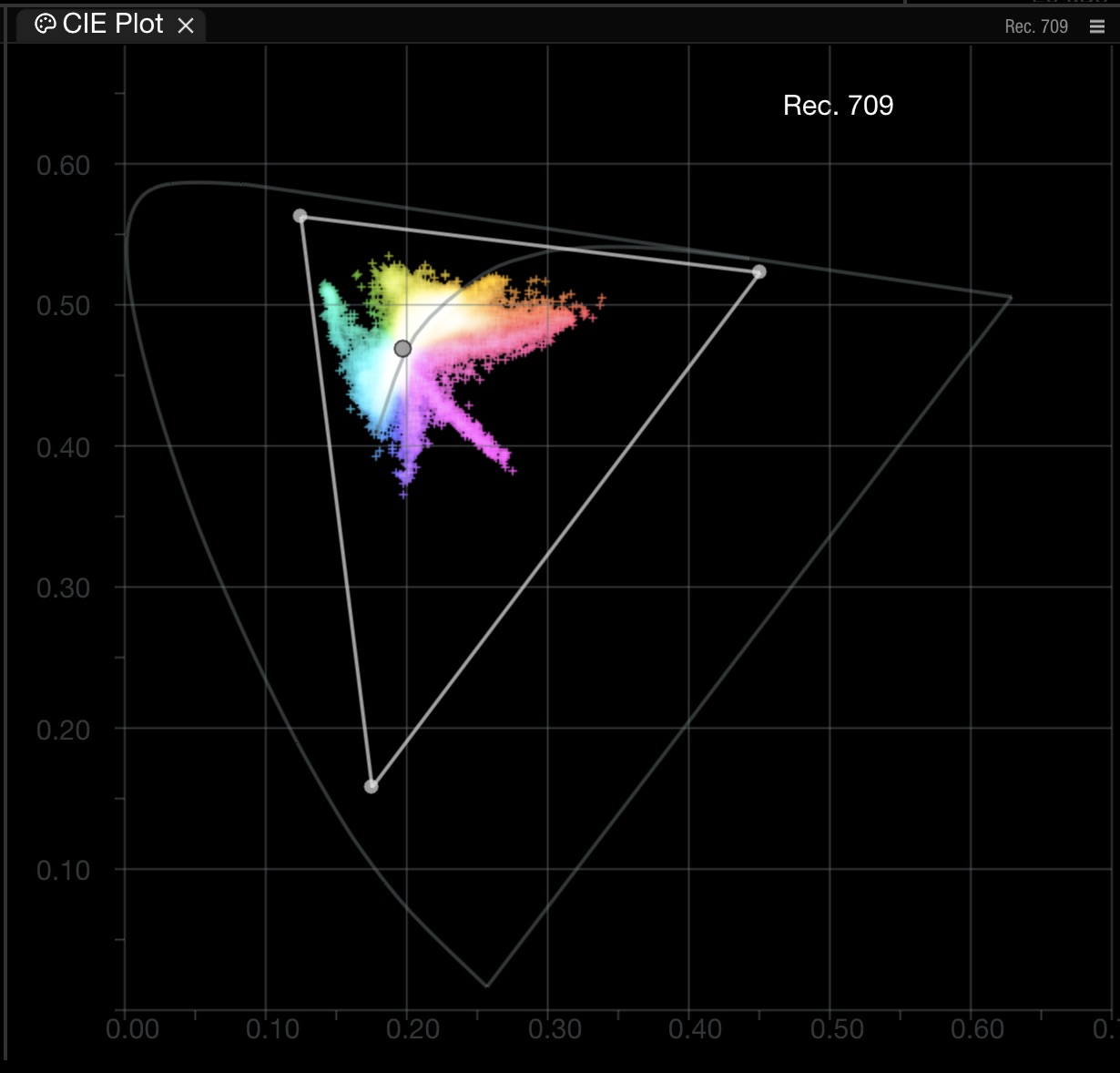
The CIE Plot visualizes the **chromaticity** of the signal on the CIE chromaticity diagram — the horseshoe-shaped footprint of all colors visible to an average human observer. Each triangle drawn on top of it is the gamut of a **color space**, defined by its three primaries and a white point. Pixels from your image are plotted as dots inside the horseshoe so you can see, at a glance, how much of the target gamut the image actually uses and whether any pixels spill outside it.
The CIE diagram is built from the **CIE 1931 Standard Observer** — color-matching functions derived from Wright and Guild's 1928–29 experiments (17 subjects matching reference lights through a small foveal field of view). The outer horseshoe boundary is the **spectral locus**: the position of every pure monochromatic wavelength from \~380 nm (violet) to \~700 nm (red). The straight bottom edge is the **line of purples**, which closes the locus between violet and red — purples don't exist as single wavelengths, they're always mixtures.
## Supported Gamuts
CIE Plot overlays the following gamut triangles:
| Gamut | Primaries / Container |
| ------------- | ---------------------------------------------------------------------------------------------------- |
| **Rec. 709** | HD broadcast / consumer sRGB (same primaries) |
| **Rec. 2020** | UHD container, wider than any current mastering display |
| **P3** | DCI-P3 theatrical and P3-D65 consumer HDR |
| **ACES AP0** | Largest gamut in production use — encloses all visible colors (primaries outside the spectral locus) |
| **ACES AP1** | ACEScg working space — tighter than AP0, still wider than Rec. 2020 |
| **ProPhoto** | ROMM RGB — wide, print-oriented still-photography gamut |
| **Adobe RGB** | \~Rec. 709 + a wider cyan/green region, common in photo pipelines |
When OmniScope cannot resolve a live OCIO working space, CIE Plot falls back to the source metadata instead: **Rec. 2020** for Rec. 2020-tagged frames, otherwise **Rec. 709**. This keeps the plot usable even when OCIO is unavailable.
## White Points
Gamut triangles are anchored to a white point — the chromaticity the display renders when `R = G = B`:
| White point | Chromaticity (x, y) | Used by |
| ----------- | ------------------- | ------------------------------------------------ |
| **D65** | 0.3127, 0.3290 | Rec. 709, Rec. 2020, sRGB, P3-D65 (consumer HDR) |
| **D60** | 0.32168, 0.33767 | ACES default, some reference projection |
| **DCI** | 0.3140, 0.3510 | DCI-P3 theatrical ("P3-DCI") — greener than D65 |
D65 is a CIE Daylight illuminant approximating average noon daylight at \~6504 K. D60 and DCI sit close on the Planckian locus but at different correlated color temperatures.

## Blackbody (Planckian) Curve
Enable **Blackbody temp curve** to overlay the **Planckian locus** — the chromaticity trajectory of an ideal blackbody radiator as its temperature changes. This is the curve that correlated color temperature (CCT) references; a "5500 K daylight" light lies on or near this locus. Useful for verifying white-balance decisions and for seeing how far your image's average chromaticity drifts from a neutral daylight reference.
## Gamut Error Check
In HDR workflows, when monitoring a Rec. 2020 signal, you can flag pixels that fall **outside P3** by enabling **Gamut Error Check**. P3 is the realistic chromaticity target for today's mastering and consumer HDR displays, even when the signal is carried inside the wider Rec. 2020 container.
Out-of-gamut pixels are rendered with an inverted color (yellow pixels above the P3 triangle instead of blue) so they visually separate from in-gamut energy.
## Custom Primaries
Custom primaries can be defined in the scope settings for non-standard gamuts (camera native spaces, vendor-specific working spaces, etc.):

## Coordinate Systems
**CIE 1931 xy** is the historical default — the diagram most colorists recognize. Its horseshoe is not perceptually uniform: small distances in the green region correspond to *much* larger perceived color differences than equivalent distances in the red or blue regions. This is the famous "MacAdam ellipses" problem — ellipses of just-noticeable-difference are tiny in blue/purple and huge in green.
**CIE 1976 u'v'** (`u' = 4X/(X+15Y+3Z)`, `v' = 9Y/(X+15Y+3Z)`) is available in 1.11.25+ and is **more perceptually uniform** — the just-noticeable-difference ellipses become closer to uniform circles across the diagram. This makes visual comparisons of gamut coverage more honest. u'v' is also the coordinate system underlying modern color-difference metrics like **ΔE** in CIE Lab/Luv.
Switch to u'v' when you want an honest visual sense of how much "extra color volume" a wider gamut actually gives you; stay on 1931 xy when you need to match the diagrams in classic textbooks and specifications.
CIE 1976 u'v' coordinate system with Rec. 709 gamut
## What's plotted, and what's discarded
The chromaticity plot **discards luminance**. A dim red pixel and a bright red pixel of the same chromaticity land on the same spot. Brightness is handled by the waveform and HDR Limit tools; the CIE Plot is purely about **which colors** are present, not how bright they are. That's why the CIE Plot is so valuable alongside a waveform — together they describe both the **position in chromaticity** and the **position in light** of every pixel.
## Directional Indicators (1.11.22+)
Directional indicators can be enabled to show drift direction relative to the target gamut — useful when gamut-mapping decisions need to know whether out-of-gamut energy is pushing toward greens, reds, or elsewhere.
## Related
* [Gamut Scope](/nobe-omniscope/scopes/gamut-scope.md) — false-color gamut-error overlay on the source image
* [Gamut Check](/nobe-omniscope/qc/gamut-check.md) — QC rule variant